Game Boy Pocket Power Regulator
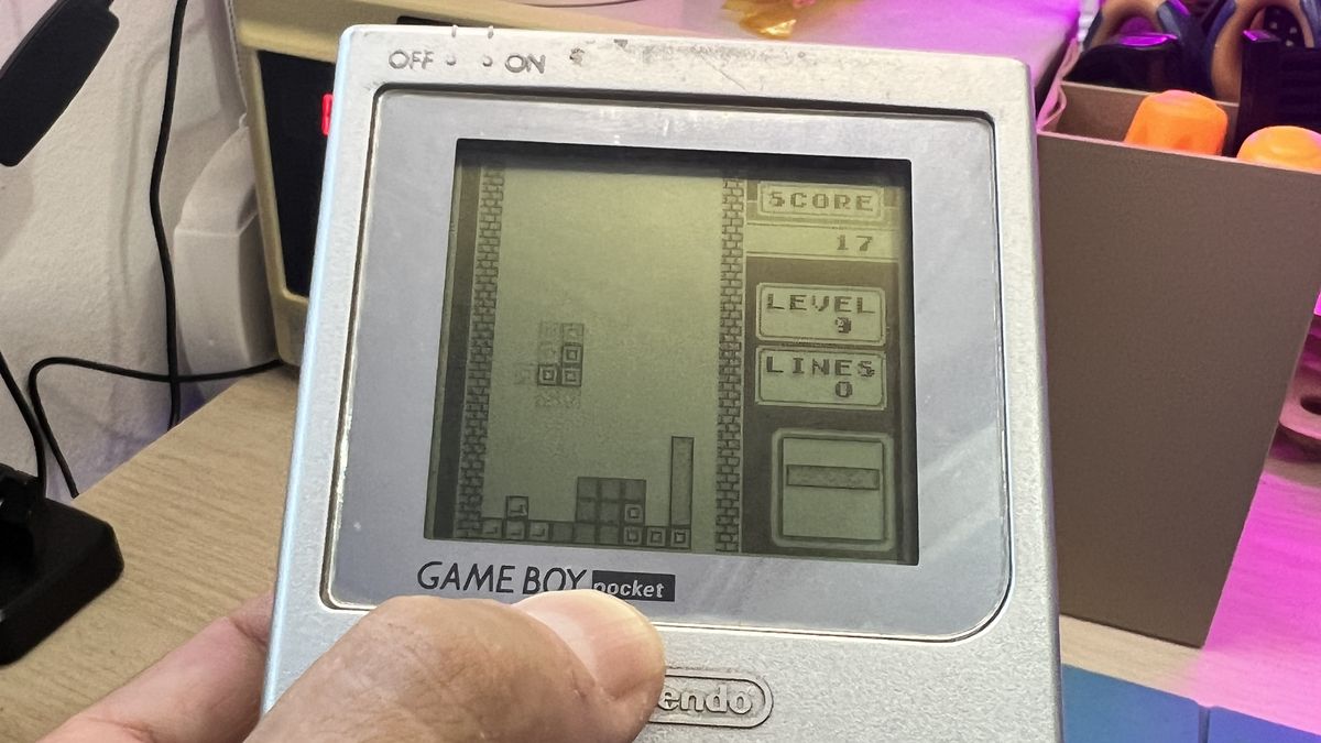
A Game Boy Pocket that wouldn't turn on: a battery leak had corroded its power module, a custom part that is no longer made. I designed a board of the same size that delivers both voltages the original screen needs, and the console is playing Tetris again.
What is it?
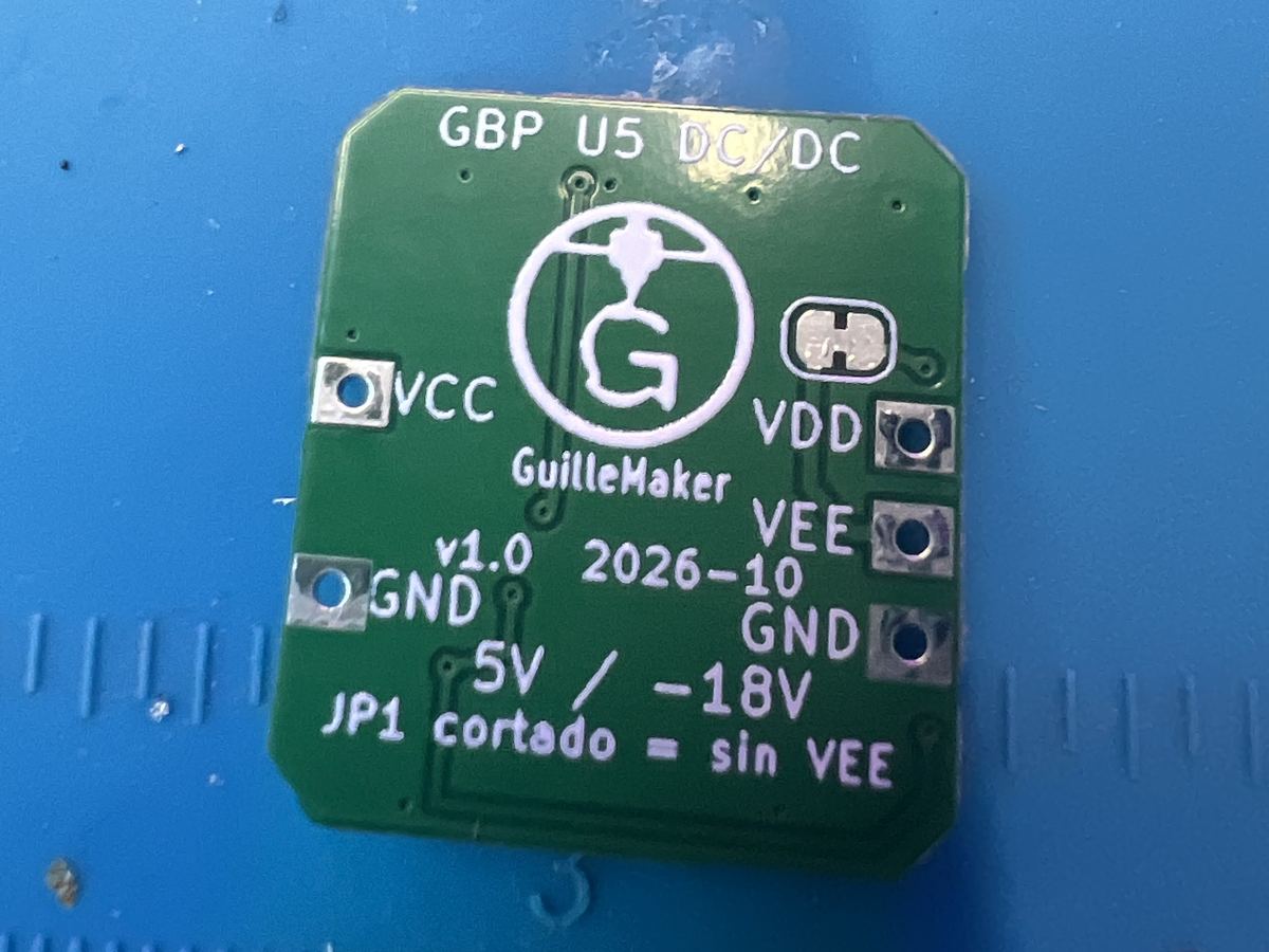
A circuit board, designed by me, that replaces the Game Boy Pocket's power regulator: the small DC/DC power board Nintendo fitted as U5 on the motherboard (part LSEP01088A1). It is the same size as the original part and has its pins in the same place, so it drops into the console as if it came from the factory. It delivers the two voltages the console needs: 5 V for the processor, the memory and the cartridge, and −18 V for the original screen. The side that faces outward carries my logo, GuilleMaker.
Signs of a failed power regulator
- The console won't turn on and the power LED stays off, even with fresh batteries.
- It turns on only sometimes, or keeps resetting.
- The screen stays blank, or the contrast wheel does nothing.
- Inside, the small module in the corner next to the batteries shows green or brown leak residue.
Why I built it
I had a Pocket that wouldn't turn on. When I opened it, the culprit showed up: a battery leak had corroded its tiny power module, the little board that turns the 3 V from the batteries into what the rest of the console needs. The motherboard, on the other hand, was fine: feeding it 5 V from outside, the console booted with its usual "ding".
The problem is that this module is a part custom-made for Nintendo, with a transformer you can't buy on its own, and it is no longer made: the ones left are second-hand and as old as the one that failed. The replacement regulators on sale, like the Pocket Mouse or the CleanPower, only provide the 5 V: they work if you swap the screen for a modern IPS one, but the original screen also needs the −18 V. I wanted to keep the original screen, with the two AAA batteries and no shell cuts, so I designed my own board.
How it works
Two voltages from two batteries
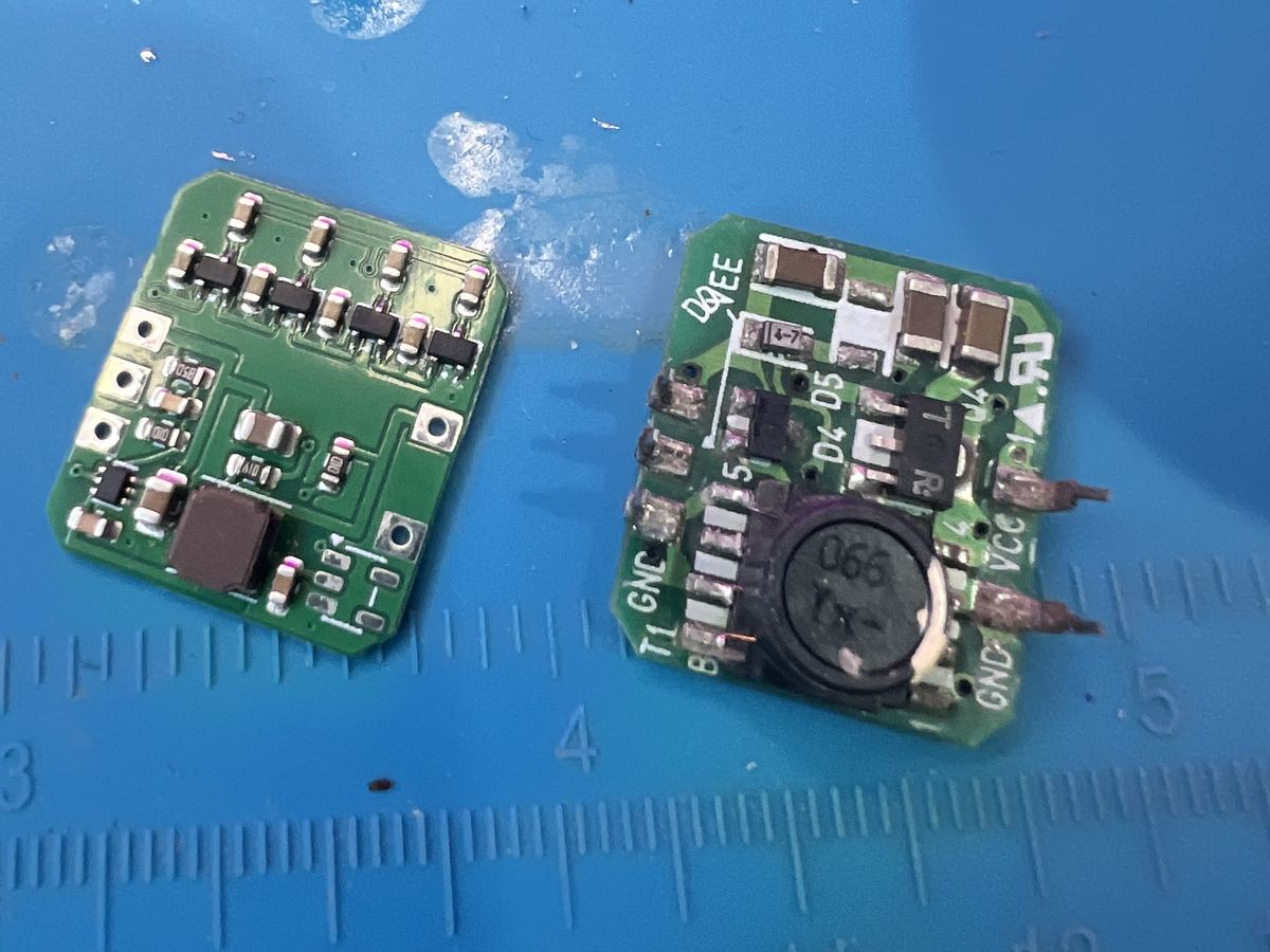
- A boost converter turns the 3 V from the batteries into a steady 5 V for the processor, the memory and the cartridge.
- Riding on that same converter, a voltage multiplier (a chain of diodes and capacitors) generates about −18 V for the contrast of the original screen.
- Every part is off the shelf: there is no need for the original's custom transformer.
- If the console ever gets an IPS screen, cutting a jumper on the board is enough to do without the negative voltage.
The same size as the original
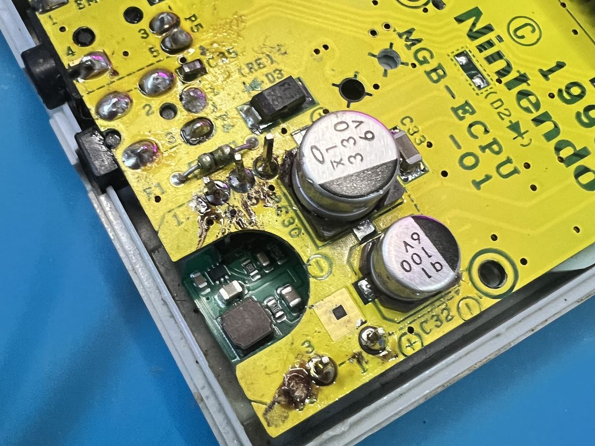
- It is less than two centimetres across and has its pins in the same position, so it fits without modifying the console.
- All the components sit on the side facing the motherboard, and the inductor, the tallest part, fits into the cutout where the original transformer used to be. The outer side only carries the logo and the labels.
You can also see how each part of the board works, with animated signals and a simulated oscilloscope, plus an installation and testing guide for buyers (in Spanish).
Explore the board inside (in Spanish) →
FAQ
Does it work with the original screen?
Yes, that is what it's for: it delivers the console's 5 V and the −18 V the original screen needs for its contrast, and the contrast wheel works just as before.
What if my Pocket has an IPS screen?
The design allows for it: cut one jumper on the board and it stops generating the negative voltage, which an IPS screen doesn't use. I've tested it with the original screen.
Do I need to cut the shell or change the batteries?
No. It fits in the original module's spot, with its pins in the same place, and runs on the usual two AAA batteries.
Which consoles has it been tested on?
On a Game Boy Pocket with an MGB-ECPU-01 motherboard.
How do I know the regulator is the problem?
If the console shows no sign of life after a battery leak and the corner module shows corrosion, it is the main suspect. Clean the battery contacts and the power switch first, as they fail more often.
Can I get one?
Yes: I put together small batches. Email me from wherever you are, and tell me which country you're in and which screen your Pocket has.
Stack
- Board design: KiCad, using the Game Boy schematics published by Gekkio as a reference
- Simulation: SPICE, to choose the values before manufacturing
- Manufacturing and component assembly: JLCPCB
- Installation: hand soldering in the console